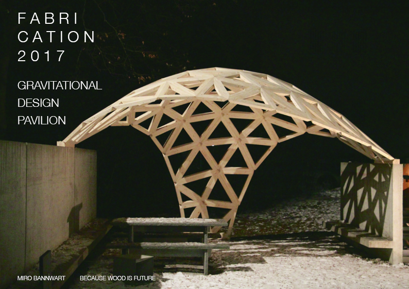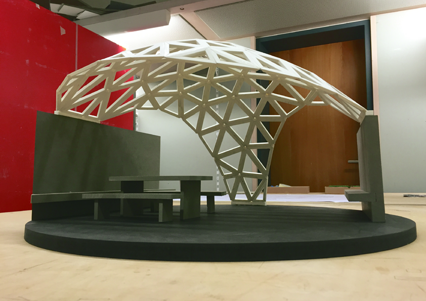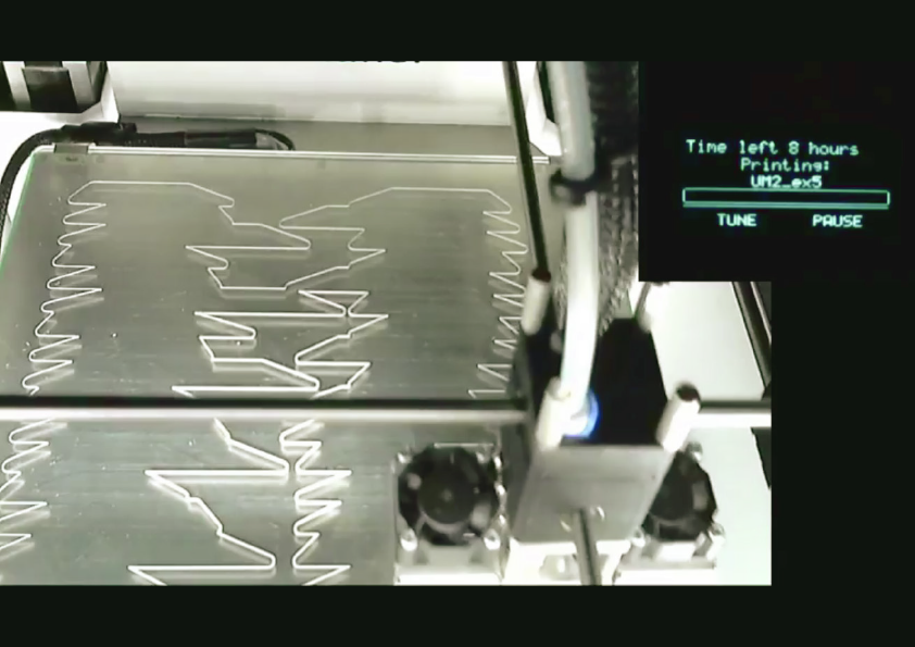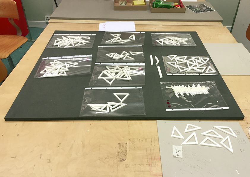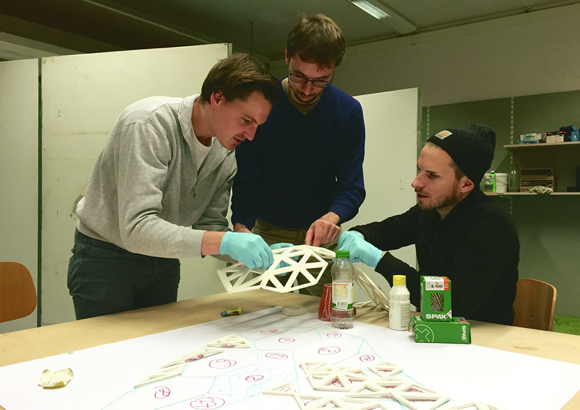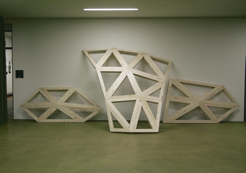
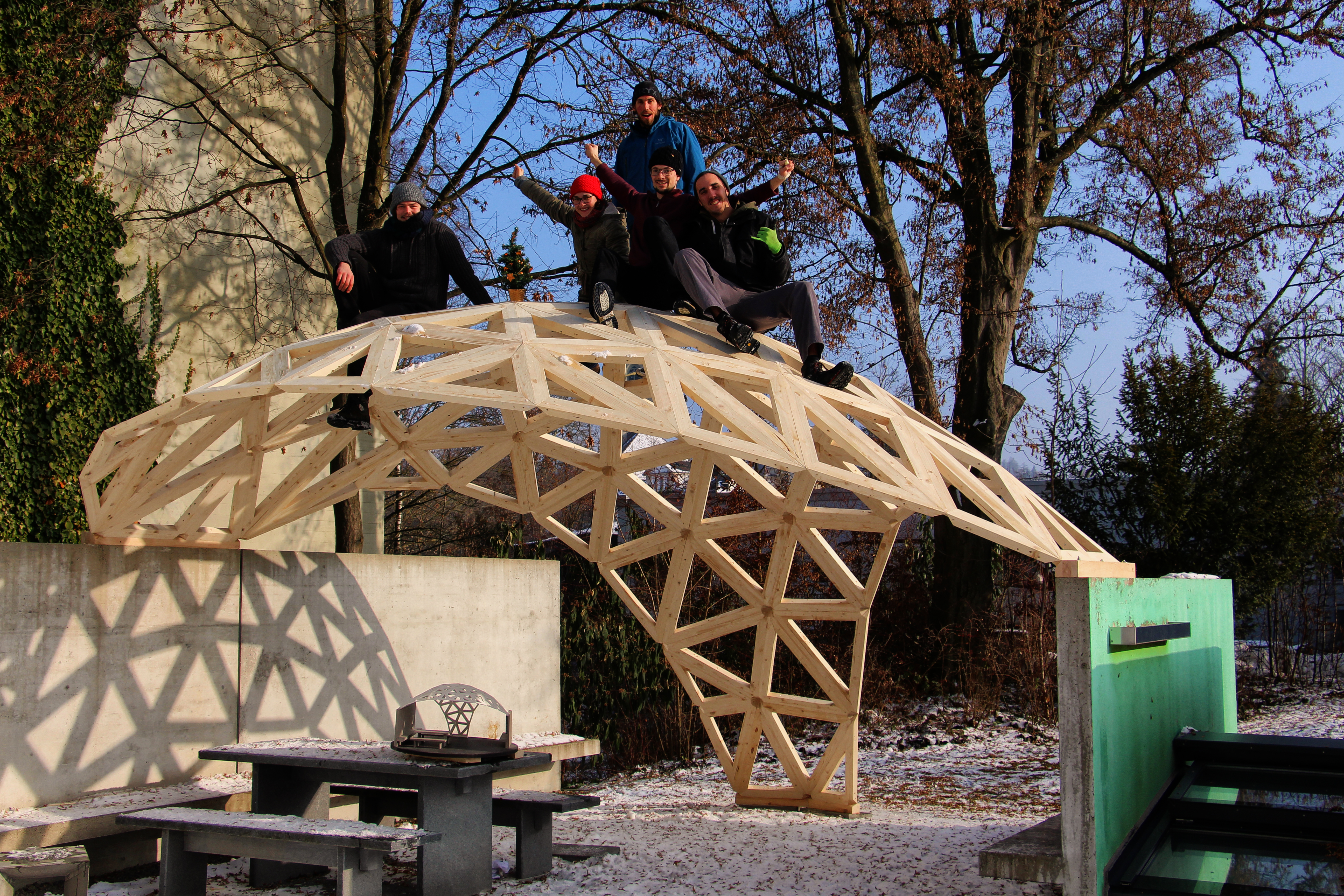
Fig. 1 The gravitational Pavilion
for more images and less text scroll down ↓ : )
Summary
The gravitational pavilion (Fig. 1), was developed in collaboration with the CNC-producer Krüsi. The double curved structure of the pavilion consists of 297 individual CNC-fabricated wood beams. To avoid complex node intersections, as well as to reduce fabrication complexity the crucial parts of the structure nodes were cut out. To make the structure stable and fabricable a high abstraction from a complex shape to simplified components as well as a two-step assembly logic was developed. A digital design to fabrication and assembly workflow was developed to accomplish this goal. The results show that the contemporary world of digital fabrication and collaboration of students with industry enables innovative small-scale projects.
01 Aim and Relevance – a process of learning
At the projects beginning stood the wish to be able to design, fabricate and assemble every physically possible complex shape in wood. To achieve this a process of learning and exploring computation and digital fabrication methods was necessary.
The project together with the preceding development steps are therefore mainly relevant in terms of acquiring digital methods. The question never had been how to develop something completely novel –more complex wood constructions had been built before. The driving question was how to learn methods enabling to build every shape in wood.
Beyond this educational value, the system is of potential use for shading roofs, winter gardens, or building extensions. A next step would be to develop an enclosed structure as well as an insulation system. This promised to enlarge the opportunities to deploy this system.
02 Stated of the Art and inspiration
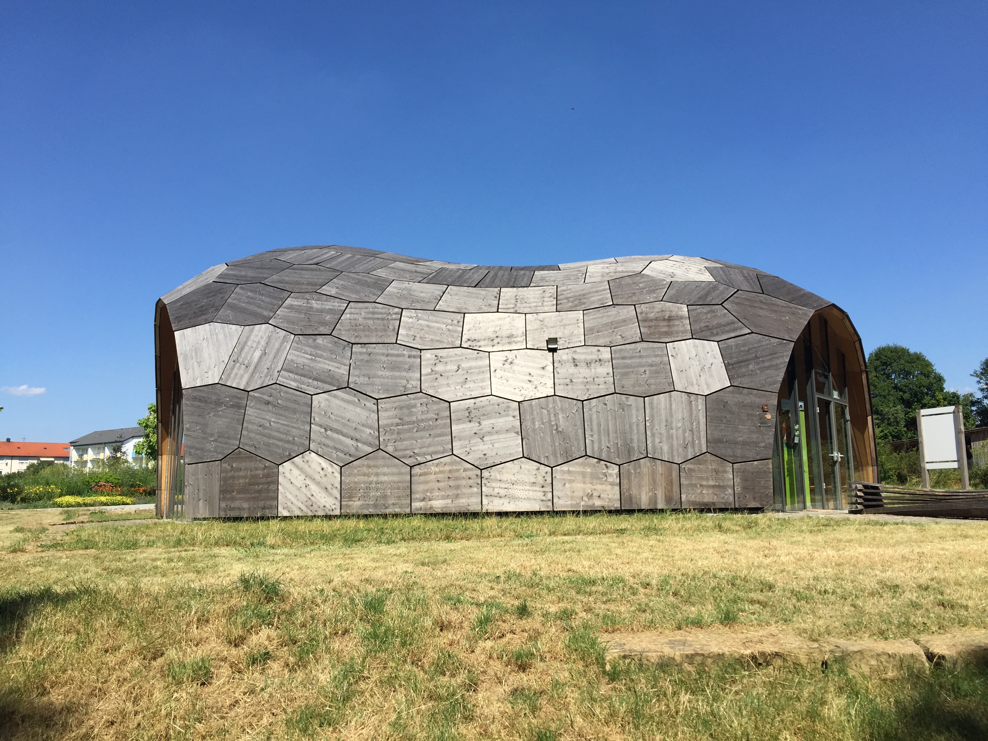
Fig. 2 Landesgartenschau Exhibition Hall ICD/ITKE, 2014
The Landesgartenschau Exhibition Hall (Fig. 2) is a beech plywood-plate lightweight structure, with a structural height of just 50 mm and spanning over 11 m. A Biomimetic approach played an important role in the development of this structure. The plate tessellation of a complex and stable shape as well as the plate connections where inspired by the biological model of sea urchins. The plates and their finger joint connections were fully robotically fabricated.1 Sophisticated agent based modelling approaches as well as a highly accurate robotic fabrication process made this project feasible.
For the project Gravitational Pavilion an agent-based surface tessellation as well as the programming and robotic milling of complex edge-patters were beyond the scope of a student project. Nevertheless this project inspired and motivated to find solutions beyond conventional wood constructions.
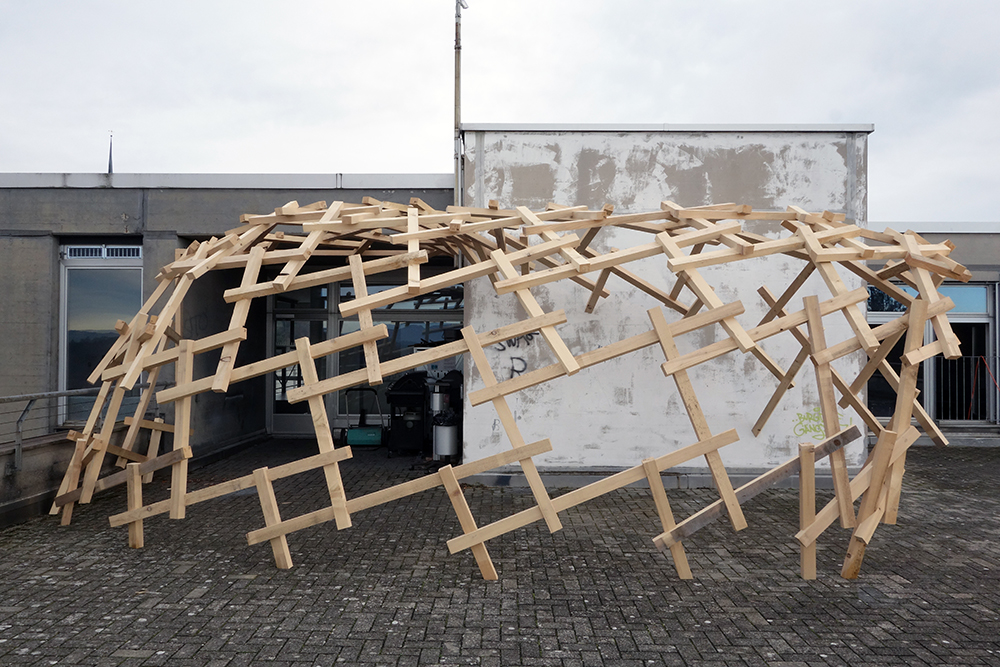
Fig. 3 Jürg Bührens reciprocal structure 2013
A further inspiration derived from a small pavilion student project by Jürg Bühren (Fig. 3).
This reciprocal structure fabricated from straight bar wood on a Hundegger CNC machine demonstrated that smaller pavilions can be built by students. Due to the reciprocal setup the ends of the beams were to a certain degree standing out of the structure. This would make it relatively difficult to cover the structure.
It was therefore attempted to develop a structure at a similar scale, and in a similar simplicity, but due to a triangular setup with a smoother surface, which could potentially be covered in a more convenient way.
03 Methods
The software Rhinoceros and the visual programming add-on Grasshopper were applied to design the pavilion shape and as well as to generate the fabricable beam geometry. The necessary skills were mainly acquired online, predominantly using YouTube tutorials. To manufacture the generated beam geometry on a CNC machine, the Cadwork software was used to export machine-readable BTL-files.
04 Results and development
Predecessors
The world of the RhinoCAD, Grasshopper and it`s plugin environment had been explored through many predecessor projects. Important steps towards simple components in complex structures were: An investigation of waffle methods which enabled waffle nodes perpendicular to the design surface, the use of the grasshopper plugin kangaroo which enables the planarization of geometry as parts of complex double curved systems, and the use of digital fabrication methods including a Kuka robot to mill wood plates. (More about on: www.miro.vision)
To extend this initial model systems towards pavilion scale, the main questions was how to speed up the relatively slow process of milling the pieces robotically out of plywood as well as to develop a system of connecting potentially up to twelve beams at one node. The ability to connect up to twelve beams at one node became necessary with the decision to tesselate shapes triangular, what is programmatically a lot simpler than tessellating shapes with planar polygons.
Design process
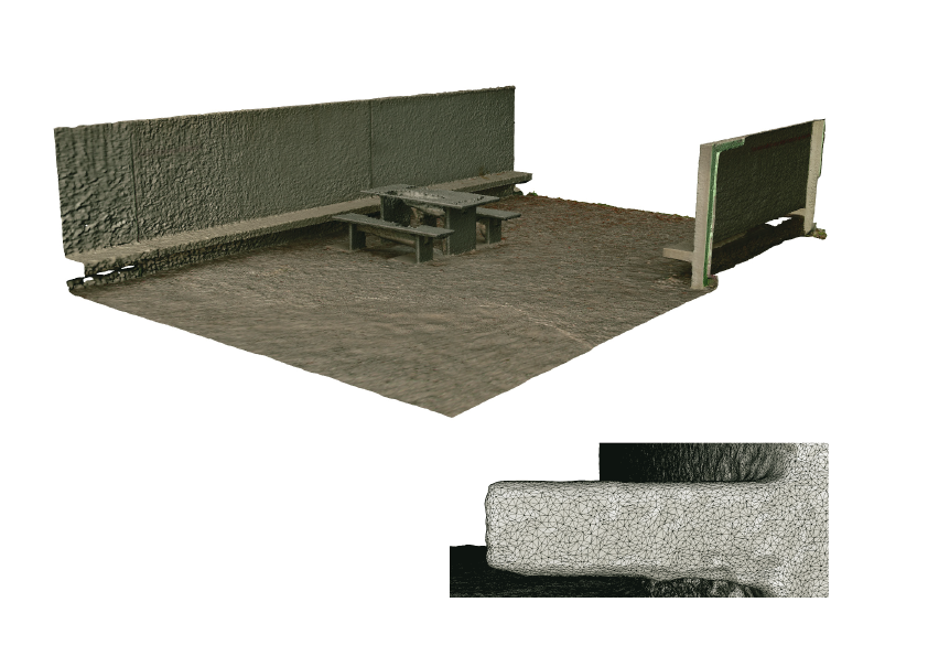
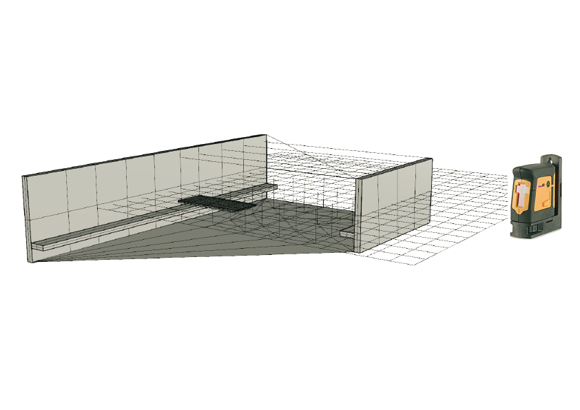
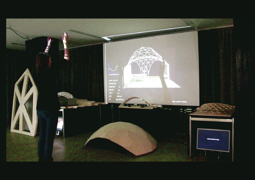
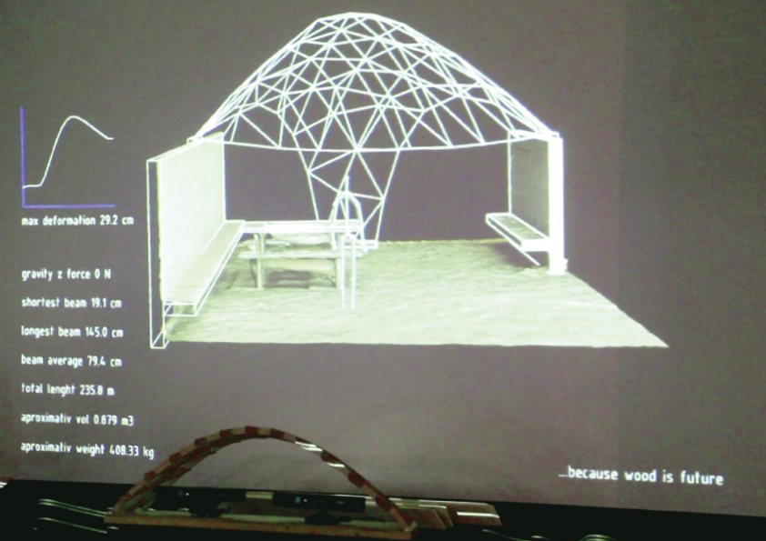
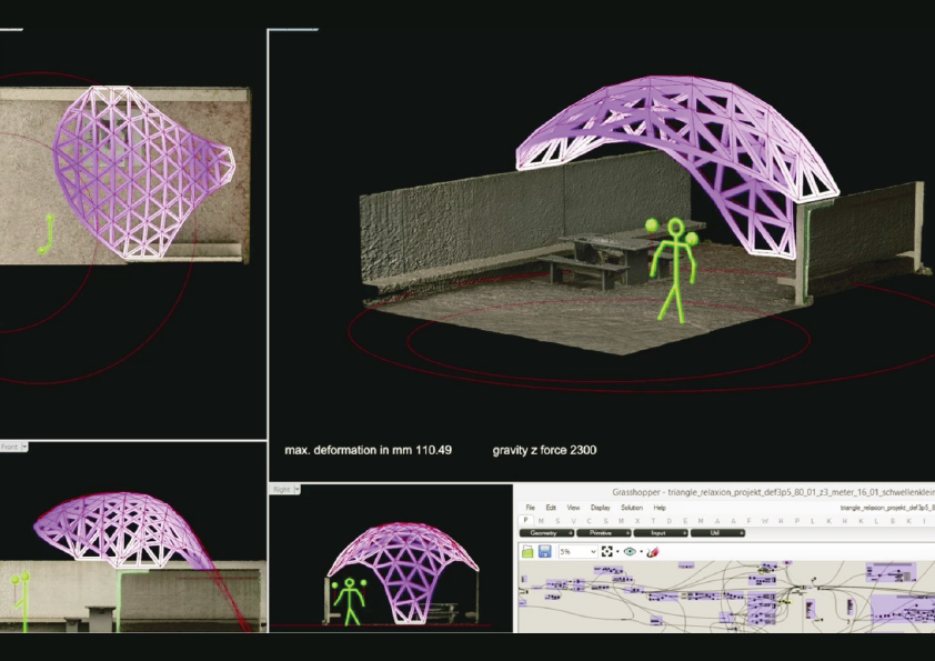
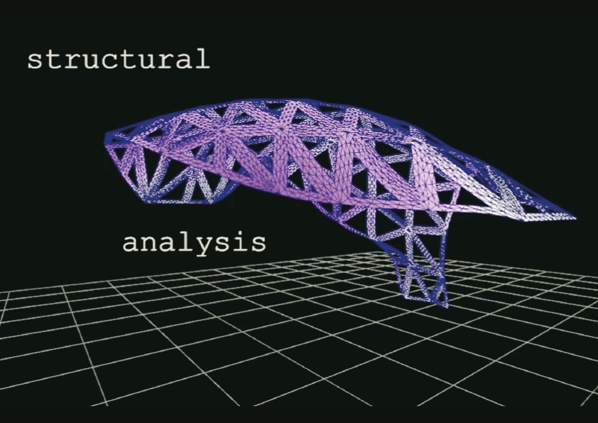
To digitally situate the design optimally in its context in front of the Univesity in Burgdorf, this context was 3D-scanned precisely by a photogrammetry method. To design the initial triangular mesh in this context, a Grasshopper- Kangaroo mesh relaxation with gravity as one of multiple parameters was combined with a motion-capturing Kinect sensor and an instant structural analysis. This setup allowed the designer to place and impact the system using hand gestures. The results were visualized and evaluated by the Karamba structural analysis, a Grasshopper plugin. Therefore the tradeoff between a gravitationally and structurally optimized hanging shape and further aesthetical or contextual requirements and constraints caused by user impacts could be played in an interactive way.
Production and geometry
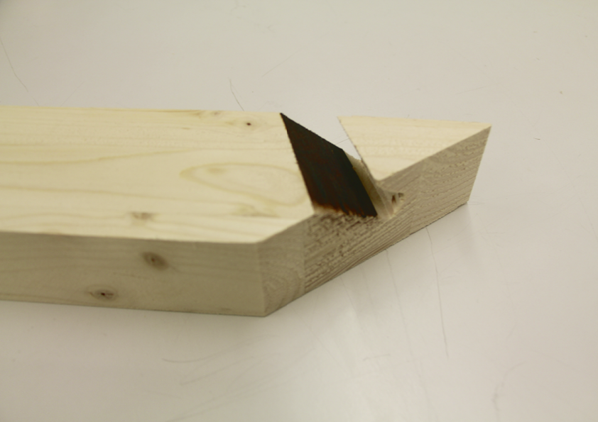
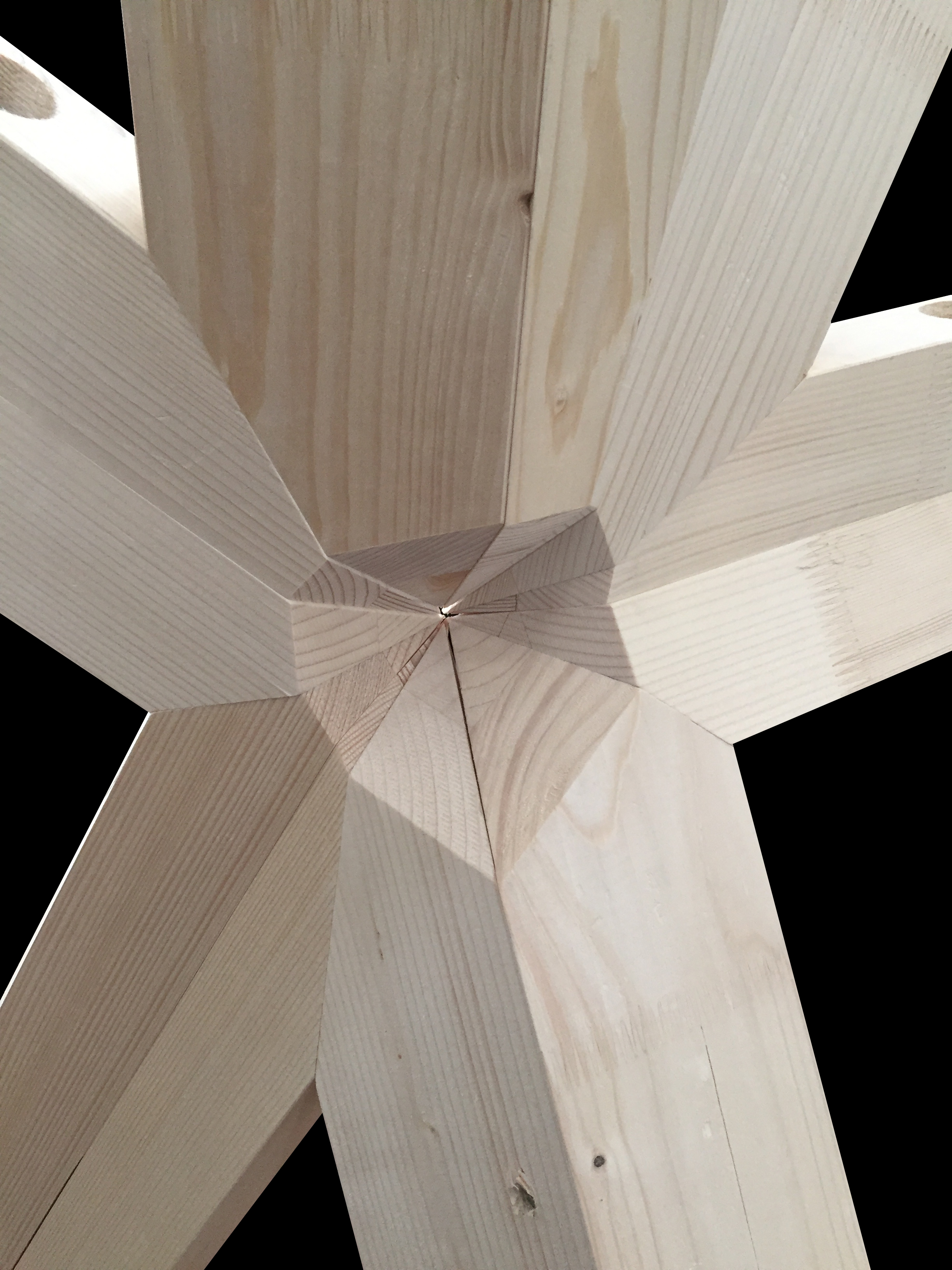 Fig. 5 Node out cut
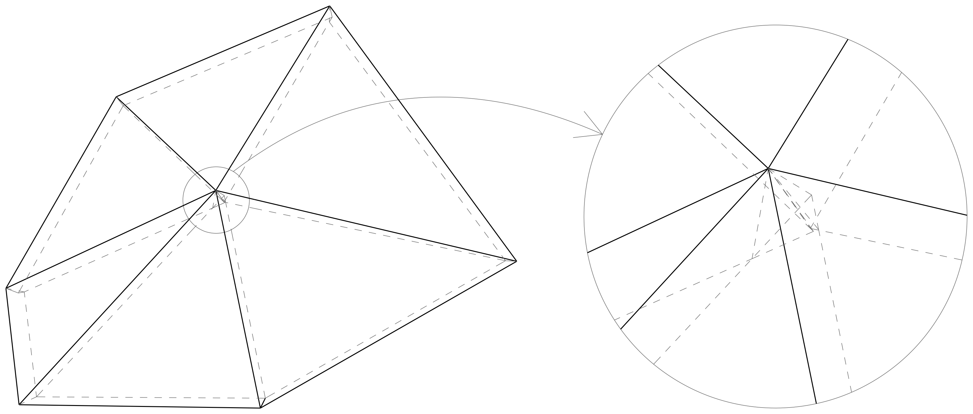
Fig. 4 Node intersection
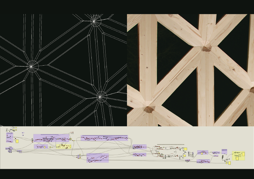
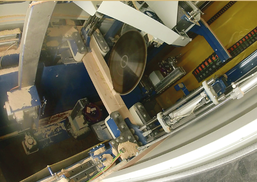
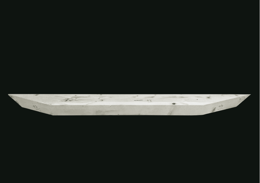
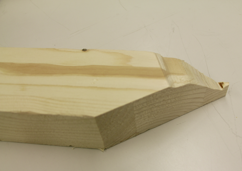
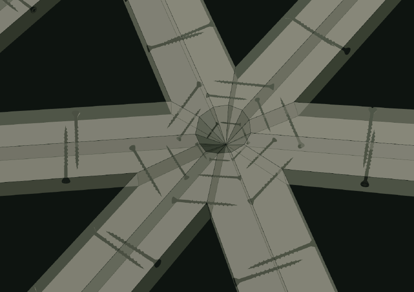
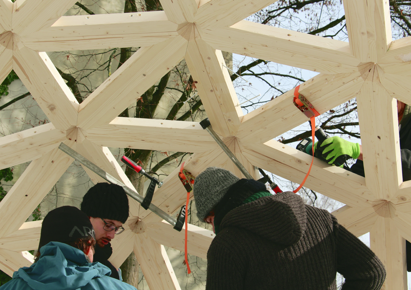
To make the production process more efficient, a code was developed that connects all nodes with its neighbors by two beams consisting of planar, and where necessary, parallel sides. This allowed cutting the beams from regular cross-sections by a modern CNC-machine with a circular saw, which, compared to robotic milling processes, is much faster. If 12 beams (6 planes) meet at one node, the upper side of the plate or beam always meet in one point. The lower offsetted surfaces (material thickness) do not intersect in one point if the base shape of the structure is irregular double-curved (Fig. 4). This highly complex node situation was resolved by cutting out the node, which also reduced the number of cuts and fabrication complexity (Fig.5)
On request, the CNC developer Krüsi and the CAD developer Cadwork offered to support this project. The beam geometry could be imported into Cadwork, which is able to export the beam geometry as machine readable BTL-files, thus storing the geometry as well as the machining data.
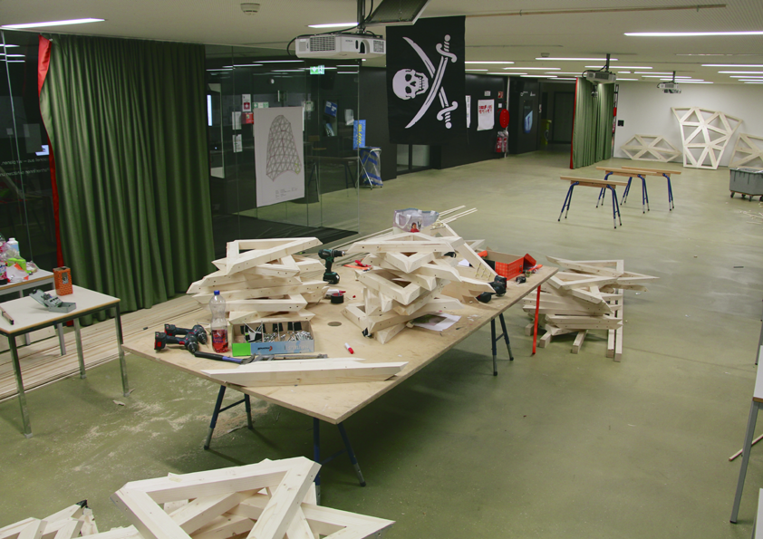
Krüsi offered to cut the beams on one of their 5-Axis CNC machines. All in all, the beams were cut in three days of production.
Assembly logic
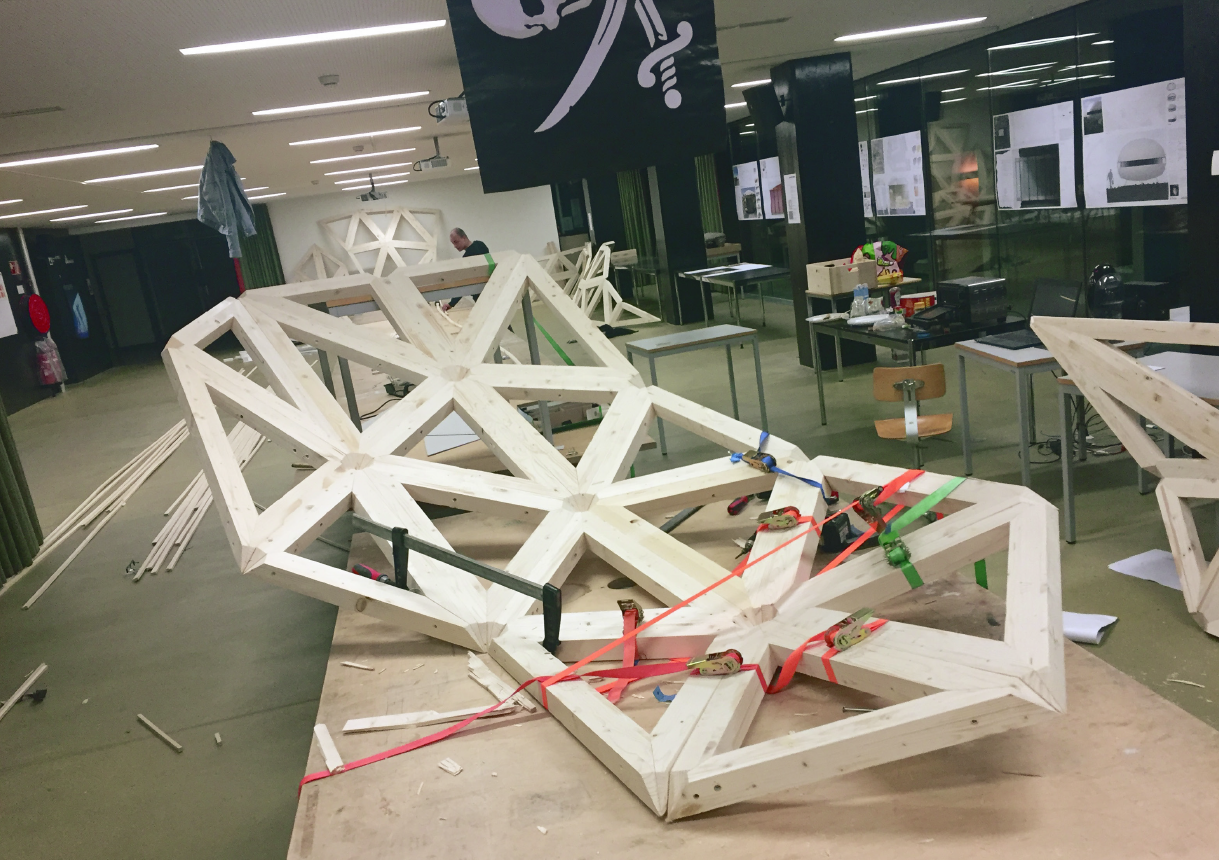
Fig.7 Segment assembly

Fig. 6 Assembly method
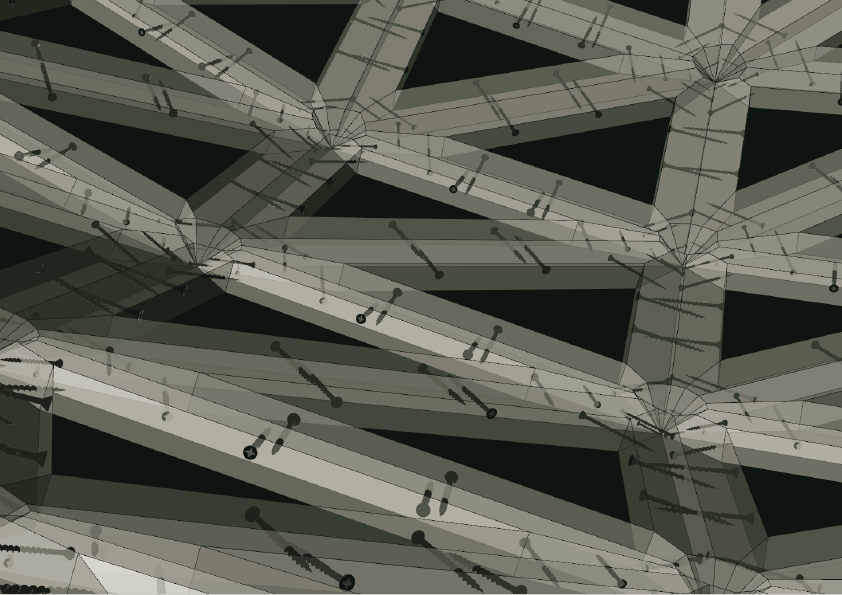
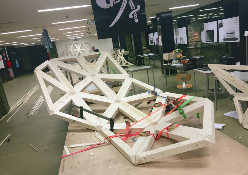
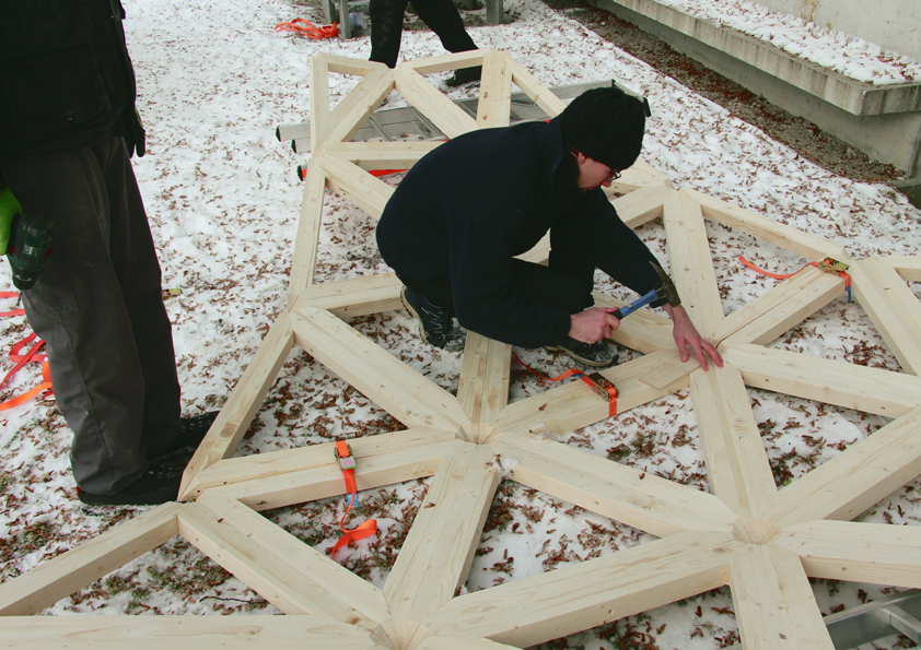
A further, but not less important, reason to connect every node with two parallel beams was the assembly and connection logic. Each triangle consisting of three enumerated beams could, in a first step, be screwed together from the outside using very stable screwing angles. In a second step, the triangles could be screwed together from the gap inside of the triangle (Fig. 6). Considering the size of the drill, an on-site beam by beam assembly with the triangular system would become very difficult because the beams cover each other in a way that makes it almost impossible to find screwing positions that are physically possible and structurally stable. The use of the two-step connection solved this assembly problem while providing a stable connection.
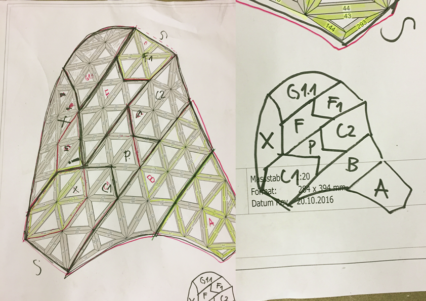
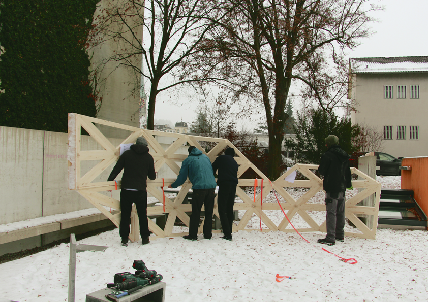
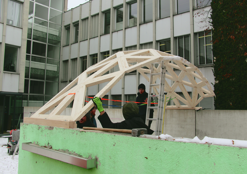
Using this method, first all triangles were assembled. Second, these triangles were assembled to segments consisting of six to eighteen triangles (Fig. 7). In a team of four carpenters and one person documenting the process, the segments could be assembled on site in one day and without a crane or additional scaffolding.
Stability
The finished structure spanned more than 5 meters with an overall structural depth of not more than 50 mm. The structure surprised by its high stability: The pavilion could withstand the weight of the five assemblers sitting on top of it. Pulled down by hand at the front bow the slightly flexible structure behaved exactly as predicted by the Karamba analysis during the design process.
Due to its slightly cantilevering shape, the pavilion started to deform slightly during the months after the assembly. Nevertheless, the connection method to screw the beams together allowed enough flexibility to avoid a structural failure.
The end in concrete
One year after the assembly, it was planned to take down the gravitational pavilion. To give it a second revival, it was suggested to use it for any further projects if anyone within the university context would have an creative Idea. Stephan Fricker a structural engineer and Professor in Burgdorf decided to use the wooden structure as scaffolding for a concrete arche. Luckily the pavilion could be used a second time and enabled a further student projects including practical work.
05 Discussion
Computational methods had been learned within the scope of the gravitational pavilion project and at the same time the learned methods motivated to explore deeper till it was finally possible to build a physical prototype. This experience of learning the field of computation and digital fabrication often reminded of the words of Buckminster Fuller:
“If you want to teach people a new way of thinking, don’t bother trying to teach them. Instead, give them a tool, the use of which will lead to new ways of thinking.” 2
It is tempting to equate Fuller’s “tool” with the ecosystem of the Rhino and Grasshopper software. This however would be a wrong limitation. Without an online accessible community of people sharing their knowledge in digital design and fabrication, the learning process of acquiring the necessary skills would not have been possible. Therefore, the understanding of the “tool enabling new ways of thinking” has to be enlarged to a net of people in and beyond the academic world, who encourage and help to accomplish projects by sharing their knowledge.
06 Conclusion
Educationally:
The main driver for the Gravitational Pavilion project was the authors strong affinity to wood construction derived of his background as carpenter. The structure demonstrates that the contemporary world of digital fabrication and students-industry collaboration can enable innovative small-scale projects.
Technically:
The abstraction of the complex double-curved shape to highly simplified components greatly reduced the fabrication complexity and fabrication time. Therefore, also the relatively low fabrication costs made the project feasible as a student project.
A further important point to make the structure feasible was the system development from the assembly perspective, which lead to the two-step screwing logic. Without this the structure could not have been assembled.
Architecturally and Aesthetically:
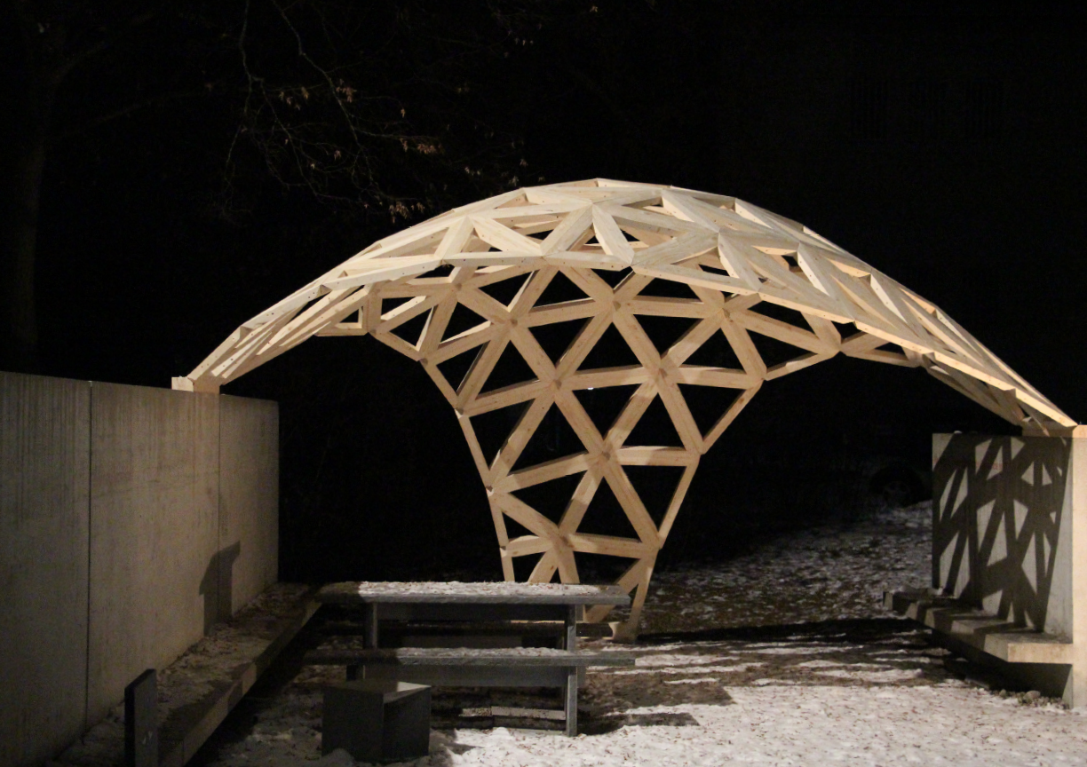
Fig. 8 The finished pavilion
The fully digital design to fabrication workflow allowed a design process within the exactly 3D scanned environment. Impacting the design by hand gestures as a part of an interactive design workflow within this 3D environment allows architects as well as people unused to CAD programs to have in an intuitive way a very contextual design experience.
From a carpentry and aesthetic perspective, the developed system especially paid off by the uniform wooden visual having reduced elements at the node. (Fig.8)
07 Outlook
Enclosure
The main purpose of every roof is to provide shelter. Therefore, developing a watertight enclosure of the structure and – in a next step – an insulation would make much sense. The main challenge of such a development would be amending the pavilion by adding further elements without losing the structure’s basic aesthetics, especially at the out-cut node.
Joints
Moreover, the joining method of the beams may be developed towards a more complex geometrical wood-only joint without any screws. This would be interesting from a geometrical point of view, but may also entail a more complex and time-consuming CNC-fabrication.
Tessellation
The triangular tessellation is very handy in perspective to the triangle’s planarity, but leads as well to the complex node situation that necessarily emerges when more than three planes meet at one node. A hexagonal or polygonal planar tessellation, where at maximum three planes meet at one node can then reduce the node complexity, so that the nodes’ out cut would not be necessary. To learn the way of agent based planar tessellations is a new adventure.
08 Acknowledgements
Thanks a lot to: Professor Jacques Wüthrich and André Marti who offered a digital fabrication seminar where the gravitational pavilion as a student project could be acknowledged. Thanks a lot to Marcel Duong and Krüsi AG for cutting all beams on one of their CNC Machines. Thanks a lot to Treppenbau AG for sponsoring the used wood. And thanks a lot to all students and friends who helped to assemble the Gravitational Pavilion.
09 References: scroll down ↓

__________________________________________________________________________
09 References
1 Landesgartenschau Exhibition Hall ICD/ITKE, 2014 Information from:
2 Quote from Buckminster Fuller from: https://www.goodreads.com/author/quotes/44478.R_Buckminster_Fuller
Images:
Fig. 1 The gravitational Pavilion, photo of the author
Fig. 2 Landesgartenschau Exhibition Hall ICD/ITKE, 2014, photo of the author
Fig. 3 Jürg Bühren’s reciprocal structure 2013, http://www.parametrismus.com/user-gallery
Fig. 4 Node intersection, self-made graphic
Fig. 5 Node out cut, photo of the author
Fig. 6 Assembly method, self-made graphic
Fig. 7 Segment assembly, photo of the author
Fig. 8 The finished pavilion, photo of the author
